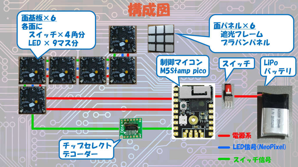
前からずっと長い間ネタ帳に入りっぱなしのルービックキューブですが、なんかルービックキューブがらみのある作品を見ていて(よく見ると今回のマウザーコンテストにも応募されている様ですが…)ふと思い出しました。 そして、「そういえばあれ作らないと!放置すると、誰かに先を越されてまたネタ帳からひとつ消えていく…」となったので作り始めました。 お蔵入り寸前のネタが発掘された感じです。
The digitalized Rubik Cube is remained in the Idea note for a long time, but I just found some Rubik Cube idea at the protopedia site, I was just impatient that someone would do something like this before I do and lose idea from the note.
長い間ネタ帳にと書きましたが、実は一度挫折したことがあります。その頃は NeoPixel の様なシリアル LED を知らなかったので、フルカラーLED と言えば RGB それぞれに制御する必要もあり、IOエキスパンダー使いまくってそれをマトリックスで時分割してそれでも大量に配線する必要がありました。今の様に基板を設計できるスキルもなく、手はんだしましたが1枚作るのに2か月ほどかかり、これはダメだと挫折したか記憶があります。
I gave up once long time ago because it's too big for me to wire the full-color led not like neopixel (not exists in the world yet) but the LEDs with full RGB pins connection and direct wiring.
その時の基板が発掘されました。 こんな感じです。
Like the photo below, I spent a lot of time wiring and hand-soldering, but it was too much for me and I have no skill to make PCBs yet.
各面に4つのスイッチを配置して同時押しにより方向を決めるというアイデア自体はその時考え付いたままでが、実現できずにもやもやしていたのを解放することが出来ました。
実際作っていると、実際のルービックキューブと操作感が似ていていい感じです。
The physical idea of rotating by pressing switches placed at four corners of each face was found at that time and I was satisfied with the improvement. It works pretty well.
実際のルービックキューブと出来るだけ操作感が同じになる様にしました。 上で説明した通り、二か所のスイッチを押すと回転する仕組みは、実際のルービックキューブの操作を参考に考案しています。
We paid special attention to the twisting action of the cube, which is similar to a real cube, without compromising the feeling of rotation.
キューブのサイズもしかりです。公式のは各辺の長さは 57mm とのことですが、丁度この長さになるように調整しました。もちろんそのまま3分割で配置すると、基板の上のスイッチとプラバンの厚さではみ出して等間隔にはならないのでその分基板の辺は短くしています。
I focused on the cube's size, which is roughly equivalent to the real Rubik's cube, measuring 57 mm on each side.
とりあえず今回はCPU周りは基板製作でのトラブルで間に合わず空中配線で乗り切りましたが、良く電線がもげてトラブったので、早く何とか基板化したい。
応募完了したら頑張ります。
➡実現済 (Finished!)
MQTTを使って、操作情報をネットワークに流していますが、ちゃんとしたディスプレイアプリを作って、本キューブと同期をさせたいです。手元で操作したキューブが揃っていく様子を大画面で大人数で共有出来たら楽しいだなぁと。揃えられたら掛かった時間をそこに表示するとかも面白いかも。加速度センサを使うと回転させることもできるかな…
➡実現済 (Finished!)
外部でディスプレイする仕組み作りたいと書きながら、実は試してみています。
別用途に作っていた、 8X8X8ドットのフルカラー LEDマトリックスキューブですが、ルービックキューブの表示出力先に相性がいいようです。
微妙に向こう側の面が透けて見えるところがいいです。
ネット連携出来ますという動画のところで、一瞬登場させましたが、ちょうどいい感じです。
残念ながら実際で見るのと、撮影された動画で見るのはずいぶん違うのでちょっと良さが伝わらないですが。
1パネルにつき、縦横2ドット分ずつの4つを割り当てました。
面同士が接する辺の部分は1ドット分開けないといけないので丁度いい感じです。逆に6×6で構成すると辺の部分の色が混じっておかしな色になってしまいます。
ちゃんと作りこみたいところです。
➡実現済 (Finished!)
外部ディスプレイとの連携の仕組みを作って、完了時間を測定してランキングする様なシステムを、Maker Faire Tokyo 2024 までには作りたいと思っていましたが、間に合わなかった…。
By Maker Faire Tokyo 2024, I would like to create a system that links with external displays, measures completion time, and ranks them. May be for also begginer mode ranking to complete just bottom part!
フル攻略出来ない人でも楽しめる様、完全1面までの時間を競うやつとかも… May be good idea preparing also beginner mode ranking to complete just the bottom face of the cube.
~~展示しているときに、解き方が判らない人は少しだけ遊んで解らないからってすぐに離れていてしまう事が多々ありました。==
~~簡単に試せるヒントモードに出来ると、ヒントモードでなんとか楽しんでもらえると思うので何とか搭載したいです。==
When I was showing at the exhibition, most of people who didn't know how to solve it often played around with it for a little bit and then quickly left because they didn't solve it any more.
一応出来てはいたのですが、バグが多く誤動作するので今のままでは逆にお客さんが離れていってしまいそうで、設計からやり直している状況です。
I developed a prototype of the hint software, but there were a lot of bugs and it behaved incorrectly. If we left it as it was, we would lose customers, so unfortunately, I am having to start over from the design stage.
➡実現済 (Finished!)
製作途中を色々と Xに投稿しようとしましたが、殆ど出来ませんでした。とりあえず今後投稿した分を以下に貼り付けていこうと思います。
I am goint to paste the post on X about this Cube below!
一応すべて最後まで揃えたことが出来たよというエビデンス代わりに動画を撮っては見たのですが、15分程掛かりとても X(Twitter) の動画時間を超えてしまいました。最初と最後以外をすべて高速再生にして投稿してみました。(やはり、見にくいですよね。)
https://x.com/TakSan0/status/1804829380839092552
空中配線のせいで、よく配線がもげました。
https://x.com/TakSan0/status/1804349897770176703
初めて投稿したやつ。一応基本動作が出来る様になった時点の動画です。明るさの調整がうまくいっていないですが。
https://x.com/TakSan0/status/1803803065839140902
一応すべて最後まで揃えたことが出来たよというエビデンス代わりにさらに動画を、今度は11分と少し早くなったので… フル攻略動画(YouTube) ▼ https://youtu.be/NgDtEdVPOKo
ネット連携で、別途製作中の「8x8x8フルカラーLEDキューブ」に表示してみた。やってみると、やはり内部に加速度センサやジャイロ入れて回転もさせたくなってきた… まだまだ改良の余地あり。 8分半と少しだけ早くなったかな。
https://x.com/TakSan0/status/1806941625056379022 フル攻略動画その2(YouTube) ▼ https://youtu.be/kYrBomL3_3s
表面パネルのカット、ハサミだとズレが目立つのでレーザーカッターで切り出してみる。 https://x.com/TakSan0/status/1807390043062804877
展示に向けて増産(焼き基板パーティー)!これで3台分 https://x.com/TakSan0/status/1808834285857820978
リフロー品質はいまいち! https://x.com/TakSan0/status/1808843818793644467
Mouser Make Awards 2024 一次通過!きたぁ!嬉しい! https://x.com/TakSan0/status/1808462338275852493
Mouser Make Awards 2024 決勝の順番はなんと、トップバッターかむかむ宣言せなw https://x.com/TakSan0/status/1811668777693774311
そして向かえた、Mouser Make Awards 2024 決勝の結果!むっちゃ嬉しい! https://x.com/TakSan0/status/1812746151738917371
という訳で、9/21~22 の Maker Faire Tokyo 2024 の出展が決まりました!
M5Stackのコンテストの直前にまたまた地雷を踏む! https://x.com/TakSan0/status/1818855705992217045 https://x.com/TakSan0/status/1818855707510501439 https://x.com/TakSan0/status/1818855709012025442
Techseker Collection に本作品を持っていく予定です。触ってみたい方、お近くまで来られる方、是非覗いてみてやってください。
こちら▼のブースにて。 技術の無駄遣い系…TakSanの製作物
https://x.com/TakSan0/status/1806979183442317476
唯一攻略した少年! https://x.com/TakSan0/status/1810451673510514785
×マークにそろえていった! https://x.com/TakSan0/status/1810451678342332450
Mouser Make Awards 2024 で決勝で優秀賞にノミネートされたため、Protopedia ブースの コンテスト決勝進出作品として展示が出来る事になりました。
触ってみたい方是非お越しください。
結果優秀賞でした。(最優秀賞とオーディエンス賞は逃しました…)
Since it was nominated for the Excellence Award in the finals of the Mouser Make Awards 2024, it will be exhibited at the Protopedia booth at Maker Faire Tokyo 2024 as a contest finalist.
If you would like to try it out, please come by.
こんな感じで展示していました。
https://x.com/TakSan0/status/1850054349235552760 https://x.com/TakSan0/status/1850372859576922458
が、小会議室という、他の作品と離れた奥まったところにあって、気付かなかった人もおられた感じだったのが残念でした・・・
初回動画 (for Mouser Make Award 2024)
The First Demo Movie for Mouser Maker Award
Mouser Make Awards 2024 決勝審査会 #マウザーアワード
決勝審査会 for Mouser Mak Awards
This is a digital Rubik's cube that has been digitized by replacing the color of each peace of the cube with Neopixels (Color LEDs) and replacing the rotating mechanical part with switches.
6枚の基板+パネルと制御用マイコンの M5Stamp Pico、LiPoバッテリー、電源スイッチ、操作スイッチ用のデコーダーといった構成となっています。各部品の詳細については以下順次説明していきます。
It consists of 6 boards with panels, M5Stamp Pico for the microcontroller, LiPo battery, power switch, and decoder for operation switches. The details of each part will be explained below.
キューブは6枚の基板を下の写真の様な展開図っぽい配置で組み立てて構成しています。 6枚中の5枚までは、基板同士はジャンパー線(スズメッキ線) を直接半田付けすることで、組み合わせています。
The cube is made up of six boards assembled in the layout shown in the photo below. Up to 5 of the 6 boards are assembled by directly soldering jumper wires to each other. The jumper wire acts as the signal wire connection and stack the each board together.
最後の1枚は、バッテリーや主電源スイッチにアクセスできるような蓋とするために、下の写真の様に信号線を電線で接続し、電源用の2ピンのヘッダピン・ピンソケット同士を合わせる形で蓋が閉まるようになっています。 (ロック機構が無いので若干浮いてしまう点については改良の余地あり。)
The last one is a lid that allows access to the battery and main power switch inside, and features 2-pin header pins and pin sockets to link the board and the lid together for power supply.
回路や基板は以下の図の様に一通り作成しました。別業者に出した 制御基板側は一寸トラブって結果的に一次審査に間に合いませんでしたが、その後ようやく到着して完成させました。(回路的には全く一緒の構成です。)
I have developed two types of original boards. One is for the outer panel with switches and LEDs and the other is for stacking the M5 Stamp microcontroller inside for control.
その後展示の為に3個増産しました。 以下の写真の様に流石に量が凄かったので、焼き肉プレートでのリフローしました。
I spent a lot of time implementing the first few panels out of 18 panels, which consist of 3 sets of 6 panels for the total. So, I cooked the rest of them deliciously by reflowing them on a grilling plate.
各面3x3マスの9マスにそれぞれフルカラー LED (NeoPixel) を割り当てて実装しています。 各面の4角には、回転方向を指示するためのスイッチを割り当てて実装しています。
Full-color LEDs (NeoPixel) are placed to each peace of the nine squares divided 3x3 parts. A switches are placed in the four corners of each surface to indicate the direction of rotation.
表面は光が変な影や反射ができるのを防止するために、最低必要な部品のスイッチとLEDのみとしました。 裏面には電源安定用のコンデンサやスイッチの同時押し対策用ダイオード、各種半田ジャンパーが実装されています。
I placed only the minimum number of switches and LEDs necessary to prevent the light from reflecting off strange shadows or surfaces. On the back side there are capacitors to stabilize the power supply, diodes to prevent incorrect recognition when pressing the switch matrix simultaneously, and solder jumpers.
なお フルカラーLEDのNeoPixel はシリアルタイプのLED で、信号線は入出力各1本ずつですが数珠繋ぎにする必要があります。各基板内で9個を数珠繋ぎにして、入口出口が決まっています。但しどの辺から入ってどの辺から出ていくのかは、パネルの位置によって様々です。部品を共通化するため、どの辺が入口になるか出口になるか選択できるようにはんだジャンパーを設けています。
NeoPixel is a serial type LED, and there is one signal line for each input and output, but it is necessary to connect them in a daisy chain. So nine LEDs are connected in a daisy chain on the board, and solding jumpers are placed each side of squired panel to select whether the side is input or output connecting to the next panel with the signal line.
各面4つの6面あるスイッチですが24個は結構多いです。もちろん M5StampPico の端子数では足りません。 端子数を節約するのによく使われるスイッチマトリクスという仕組みを使っています。 縦横網目状にスイッチを配置し選択信号の出力と読み出し信号の入力端子に分けます。選択信号を時分割で出力しておいて、選択されている行または列の読み出し信号の端子状態を読み出すことで、端子数を大幅に節約できる仕組みです。 今回の場合は選択信号を各面に割り当て、読み出し信号を各基板の4つのスイッチに割り当てましたので、入出力で10本の端子を使うことになります。
Because there are six panels, with four switches on each panel, the system need totally 24 switches are quite a lot. Of course, the number of pins with M5StampPico is not enough. So I use switch matrix like the diagram shown below, to save the number of pins. In this case, the selection signal was assigned to select panel and the readout signal was assigned to the four switches on each board, so totally 10 pins were used for input and output.
また、スイッチマトリクスを使う場合の注意点として、複数キーを押すシステムの場合逆流防止ダイオードを入れておかないと関係ないキーを誤検知してしまう問題があるため、"同時押し対策用ダイオード” を全てのスイッチに入れています。 興味ある方はスイッチマトリクスについてネット検索してみて下さい。
Furthermore, since this is a system that requires multiple presses at the same time, due to the characteristics of the matrix switch, a diode is placed in series with each switch to prevent misreading due to current backflow.
内部も基板を設計したのですが、基板設計業者との指示間違い等でトラブルでトラブり、Mouer Award の一次審査時点で完成は間に合いませんでした。しょうがないので今回は空中配線です。ひとまずはプロトタイプということで…
(不安定で配線がもげたりトラブったので、早くは完成させなければ!)
下の写真の様に接続しています。 CPUと面基板及び、チップセレクトデコーダー(後述します。)と面基板は 1.27ピッチのコネクタを介して接続しています。それ以外は直接接続しています。
I used direct wiring to connect M5 Stamp in the prototyping process, as shown in the photo below.
その後上がってきた基板で、作り直しました。配置が微妙な点以外は特に問題もなく、初回基板ですんなり動きました。構成はこんな感じになりました。
For the second try, I build the original board with M5 stamp Pico and other parts on the board.
LiPo バッテリの給電と、充電コネクタとLiPoバッテリーの切り替えを行います。
The power switch selects the connection to charging connector or the LiPo battery connector.
とにかく小さくて且つ将来的にネット連携等外部とやり取りしたという事で、M5Stamp Picoを選択しました。 余っている端子は入力専用端子が1端子しかありません。音を出す仕組みも入れ込みたかったのですが、もう1ピン程多いやつが欲しい感じで検討中です。
I chose M5Stamp Pico that is completely fine because it is small enough to fit in the cube and has a wireless communication future in it to send a various kind of data outside of the cube. I wanted to include a part of making a sound, but need another pin and no more pin are available, so I've given up this time but next time.
M5Stamp pico自体のスペックは5V推奨なので本来なら昇圧が必要なのですが、使っている電源レギュレータ自体は範囲内なので、Direct で入力しています。そのかわり、電圧不足になってくると早めに不安定になるはずと思っていましたが、その前に NeoPixel LED 側の方が不安定になって消灯してしまいますので、そうなったら充電すればよさそうです。
The specifications of M5Stamp Pico itself recommend 5V, so boosting is normally required, but I noticed a range of voltage for the power regulator used for M5stamp is within the range, so I input it directly. Instead, I thought that it would become unstable quickly when the voltage became insufficient, but the NeoPixel LED became unstable before that and turned off, so I decided not use it. Seems to be working all right.
スイッチマトリクスの所で、スイッチに10本の端子が必要と書きましたが、実はM5Stamp Picoにはこんなにたくさん端子が無く足りません。 そこで多い方(面選択側)の端子に、チップセレクトデコーダーを接続しました。 これは 3本の 0~7 を入力すると出力側の 8本の端子のうち1本が LOW 状態になるもので、同一バス上に接続されるデバイスを選択するのに使われるものです。(74HC138 というデバイスです。) 1つデバイスは経由してしまいますが、CPU側からの信号は6本が半分の3分で済み7本で足りるようになります。
In the writing at the switch matrix above, I wrote that the switch requires 10 pins, but the number of pins is still too many. Therefore, I connected a chip select decoder that when three 0 to 7 are input, one of the eight output pins becomes LOW. Now the required pins are 7.
また、各面の選択信号はユニークにしないとどの面が選択されたかわからなくなります。これも基板自体を共通化するために、半田ジャンパーで選択できるようにしています。
In order to make the panel board with one design, a solder jumper is placed to set which selection signal to be connected, which makes it possible to set which side it will be on.
外部パネルは、LEDを直接見た場合のまぶしさと RGBが見えてしまうのをぼやかすためと、金属にあたってショートするのを防ぐためにプラバンを被せる構成としました。 また隣り合う光がまじりあって境界線付近の見てくれが悪くなるのを防ぐために、分光フレームで囲っています。 分光フレームは 3Dプリンターで作成しました。 基板の穴にねじ付けしている形です。(もう少し美しくフラットにはしたいけど今後の課題ですね)
I used a plastic plate cover processed to prevent direct glare from the LED and to prevent short circuits. Parts for light divider were created using a 3D printer.
パネルの試作は CADで作成した図をはさみで切って貼り付けましたが、若干のズレで引っかかりがひどいので精確に切り出す為にレーザーカッターを使いました。(初レーザーカッターのデビューです)
I used a laser cutter to process the panel to cut it out accurately because it was easily caught due to slight misalignment.
パネルの取付は、外側からビスで止める為にナットを圧入した留め具を 3Dプリンタで作り、裏に固定するようにしました。
I used a 3D printer to build nut holders as well.
回転方向決定の仕組みが本作品の肝となっています。これを思いつかなかったら実現できていませんでした。 スイッチ一つでは下記の図のように、赤い矢印の方向に回転させるか緑色の矢印の方向に回転させるのか、判断が付きません。
The mechanism for determining the rotation direction is the most important key solution of this system, because pushing one key is not enough to decide the direction.
実際のルービックキューブを回してみるとわかるのですが、ひとつの列を回転させるときには2か所をつかんで回している場合がほとんどです。最近の競技用のスムーズに回るキューブは1本指でもスルっと軽く回せるらしいですが、今回はその辺はおいておき通常の使い方を想定とします。 この点に着目して、回転を認識する方法を検討しました。
Then I found out that when I turn the cubes by squeezing, two parts of the cube are touched with the hand in either direction to rotate, like the arrows in the photos below.
(※すみません。ここの写真に実際のルービックキューブをつかんでいる写真を使いたかったのですが、どこかに紛れ込んだのか、記事作成時にどうしても見つかりませんでした。後日置き換えます。)
同一回転軸上にあるスイッチのうち2つ以上が同じ方向にあるとき(下記の図ではオレンジ色の4つのパネルのうちの2つが押された場合赤色方向)に回転させるようにしました。そうすることで、実際のルービックキューブの操作感覚を損なうことなく操作できるようになりました。
I decided to press two or more switches on the same rotation axis make a decision which way to rotate. (In the figure below, if two of the four orange panels are pressed, the direction will be redone)
デジタルならではの長所があります。ソフトウェア次第で色々機能を搭載出来る事。ついつい力が入って色々と実装しました。 下図の緑の場所を同時押すと呼び出される機能です。
As a digitalized benefit, I have developed a many features with the software. I made some special key sets to push at the same time, that call special function shown pics below.
コンテストでの時間制限が2分と余りにも短くて、すべてを紹介できなかったので、ここで書きます。
回転操作したら順次回転して見える様にアニメーション表示する様にしています。操作している感があります。
The cube physically does not change shape at all, so rotation animations are very important for users recognize rotation movement. The animation that shows how the color of the panels shifts when it rotates is very important as a basic function, so I took special care in developing it.
同じ面の4角のキーを全て同時押しすることで、自動的にシャッフルすることが出来ます。15ステップ分の乱数で操作する様にしていますが、まだまだシャッフル具合は足りない気がします。
A real Rubik's Cube needs to be shuffled by yourself before playing. But in this one, all you have to do is pressing all the four switches on the one panel at the same time, and it will shuffle automatically in an instant. It will rotate about 50 times at random.
万が一おかしくなった時の為に一応リセット機能は組み込んでいます。ちょっと呼び出し方は難しいですが。 ESPリセットの仕組みを使っています。
A reset function is very important in case something goes wrong or the device stops working.
割り当てられたキーを操作することで、LEDを全て消灯させた後スリープ機能に移行させて、低消費に入れてバッテリーの消費を抑えることが出来ます。 LightSleep を使っているので、クロックは止まっていますが端子の状態は保持していますし、DeepSleep 程はバッテリーは低消費にはなりません。
By switching off all LEDs and then switching to light sleep mode, the device will enter low power mode and reduce battery usage. Since this is not deep sleep, the clock is stopped, but the pin's state is maintained, so it does not save a lot of power, but it is effective in reducing the large current of LEDs, etc.
操作を一切していない気かが5分以上続いた時オートパワーオフする機能です。 とはいっても、本当はオートパワーオフにしたかったのですがスリープ機能と同じで LightSleep状態です。ちょっとは電流流れてしまいます。
Auto power save. This function automatically goes into sleep mode if no operations are performed for more than 5 minutes.
キーを押すことで、一つ前の状態に戻す機能です。最高シャッフルした直前まで戻すことが出来ます。
This is the Undo function just like commonly found on computers in the world, and is also the great advantage of digitization that cannot be achieved with a real Rubik Cube.
キーを押すことで、Undoした操作をやり直す機能です。
The opposite of Undo is the Redo function, which is also common on computers in the world.
用事が出来て、途中まで解いていた状態を保存したり、その内容を復元したりできいます。内部のフラッシュロムに搭載されている SPIFFS 内部に書き込んでいます。
今の所1か所にしか保存できませんが、保存先を複数選べるように拡張したいところです。
This is a function to Save or Load current state into a file placed in an internal non-volatile memory with SPIFFS file system.
保存内容は、シャッフル後開始時の各面の状態と、現在の各面の状態、そしてシャッフル後からのヒストリー(Undo/Redo 用) すべてです。2000操作分のヒストリーバッファーがあるのでまず溢れないとは思っています。
The save data include current color state of each panels and history data for undo / redo or replay mode.
ヒントモードに入ると、次に操作すべきキーを点滅して知らせてくれます。
フルヒントモードと、キーを押したときだけヒントを点滅するモードがあります。
実はこの機能はまだテスト段階で完全ではありません。
Hint mode shows how to solve the Rubik's Cube, with the LEDs blinking to indicate where the switches to press are located.
アルゴリズムもかなり複雑ですし、ちゃんと実装するには解き方自体をちゃんと理解する必要がありそうです。
ヒント通りの操作から外れて、再計算が必要になったタイミングでバグが発生してかなりおかしくなるという問題を筆頭に沢山バグがあります。また、ヒントのパターンも一部だけ実装されていて網羅は出来ていません。
(デモ動画はその部分の解き方だけで実装しました。)
とはいえヒント機能は、高度なソフト部分になるので電子工作中心のコンテストである、本コンテストでの完成は必須ではないと勝手に言い訳しています。
今後の発展にご期待下さい。
~~I tried for a prototype, but It was a little buggy and not perfect because the algorithm to show solve are quite difficult and under redevelopment to work perfectly until demonstrated at the Maker Fair Tokyo 2024. ~~
Maker Faire Tokyo2024 に向けて少し進化(問題ありでも動く様に)、その後しっかりデバッグして完成しました。但し、あまり万能ではありません。
▽こんな感じ(ヒントモード完全動画)です。10分越えと少し長いので冒頭だけでもご覧ください。もちろん興味ある方は最後までご覧ください。 https://youtu.be/tPQVp4ZYuxQ
私が最後まで揃えた履歴を固定のデモデータとしてプログラムに組み込んであります。 あまりにも長いのでもっと上手い人の、華麗で最短の操作をでもデータとして組み込みたい。
Demonstration program made with the record of my bad play :) show moving automaticary from beggining to solve compleate.
シャッフル直後からのUndo用の履歴データを基に、操作を全て再生する機能です。後で自分のプレイを見て反省するなり、得意になるなり自慢するなり好きにして下さい。
The replay function plays all operations from the beginning just after shuffling to the current point using the historical record for undo operation.
ネットを使用して外部ディスプレイデバイスとの連携も行えます。 キューブ自体は LED 以外の物で外見を損なったり、有線接続でコードが邪魔になったりさせたくなかったので、こだわってワイヤレスで通信を行いつつディスプレイに表示できるようにしました。ネット経由で MQTT 使って連携するか、ESP-Now を使って連携するか、環境によって選ぶことが出来ます。
It is possible to send information to an external display. Connecting with a wire would prevent easy operation while playing, so I insisted on making the external display without wire connection. In addition to displaying the current status of the cube, it can wirelessly transfer information that is difficult to show with just the LEDs on the cube and display it on another M5Stack Display. Can select either MQTT or ESP-Now with your environment.
下の写真の様に、下の段から何段まで攻略したかを示すステップの数値表示 (0 ~7 ステップ迄あります) とそのアイコン表示、現在のステップ迄の到達時間、現在のキューブの状況が表示される他、隠しコマンドによって呼び出された機能がディスプレイ上に文字で表示出来る様にもしています。
As shown in the photo below, the Icon and the numerical display of steps (from 0 to 7 steps) indicating how many steps have been completed from the bottom, the arrival time to the latest step, and the status of the latest cube are displayed., functions called by a specific switch combination, commands can also be displayed as text on the display. I chose M5-Stack Series for the external display parts and you can select one of the M5 series with LCD on it.
WiFi 経由でネットに接続し MQTT に操作情報を送ることで、外部のディスプレイ等に現在の状態を表示することが出来る様になります。
一旦有効にした WiFI 及び MQTT の接続を切ることで、ネット連携が不要になった時の消費を押えれるようにもしています。
一回動かすと、様々なパネルが動くし、それをアニメーションする必要があるのでとても苦労しました。 どれを動かしたとき度のパネルが動くかや、どのキーの組み合わせでその方向に動くのかなど、全てがテーブルとなっていますが、テーブルが多すぎて苦労しました。
Since it is difficult to turn regularity into a pattern, I created many tables and implemented it. It was necessary to always be aware of the rotation, and it was very difficult to understand the movement of the panel as it moved from one surface to another, making software development quite difficult.
単純なアプリではありますが、実はFreeRTOS の機能を使って3タスク+1割り込み構成となっています。
割り込みではスイッチスキャン、タスク系はキースキャン結果の解析系のタスク、表示(アニメーション)系のタスク、MQTT のネットワーク系のタスクの3段構成です。
表示系を別タスクにしているので、操作後のアニメーションが少し遅れて見えますが、高速で操作してもすべて操作はバッファリングされ、アニメーションされます。バッファはかなり大きくしているので多分オーバーフローすることはないはず…
In order to correctly operate switches, LED animation, network coordination, and other items that each have different control timings, I divided and manage tasks using an RTOS.
Thanks to this, even if I press the key several times, all the consecutive key presses are buffered, and the animation processing runs smoothly without interfering with the main processing.
猛特訓をして何とか自力で攻略出来る様に 試みておりましたが、地雷が次々爆発し(バグ発生) 滞ってました。未だに、一部カンニングペーパーが無いと進めないところがあったり、記憶があいまいで間違えて捜査して Undo してみたりしていますが、何とか自力で出来る様にしたい‼
なりました。
When I first developed this, I had no idea how to solve a Rubik's Cube.