てのひらOBD-CANモニタ
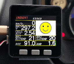
完成
5104
完成
5104
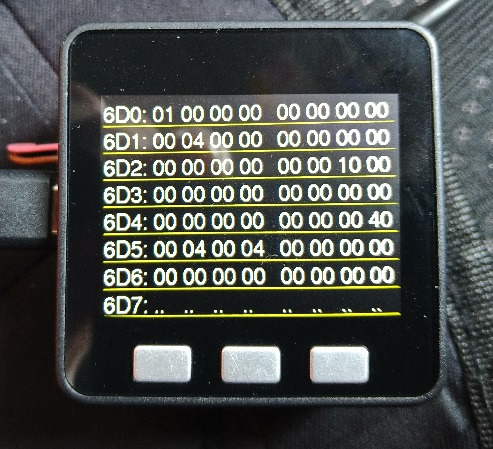
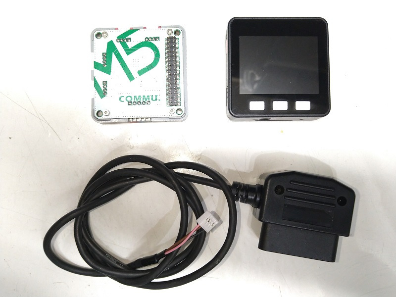
M5Stackを使った汎用OBDII-CANモニタです。
(自動車車両に接続する場合は、自己責任でお願いいたします)
General-purpose OBDII-CAN monitor using
- 動画
-
- 開発素材
-
デバイス
ツール
- システム構成
-
- ストーリー
-
- メンバー
-
-
- naka_mobile @miev
-
- 企画/設計/開発
- 製作者
- プロトタイプ製作
-
- 関連イベント
-
-
 M5Stack Japan Creativity Contest 20222022-07-15 開催
-
- 同じニオイがする作品
-
-
 昭和育ちなおっさんたちは黒電話を携帯する夢を実現する...
-
 陣痛共有デバイス「Happy Pain」
-
 デジたま2 the AI
-
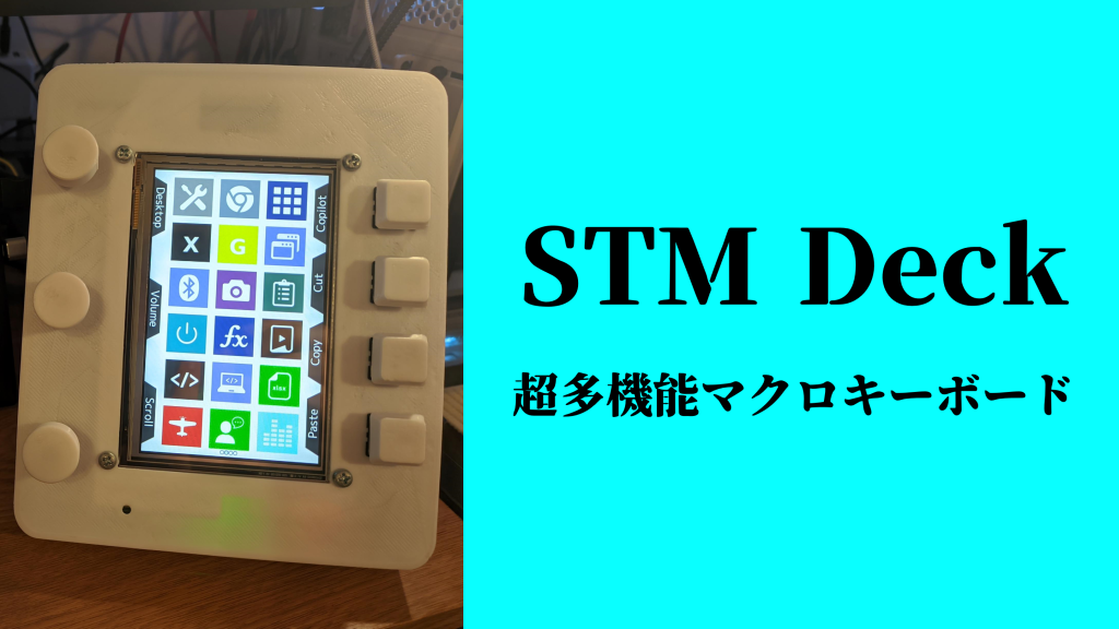 STM Deck
-
Proto lovers ♥