デジタルなルービックキューブ
完成
© CC BY 4+
1776
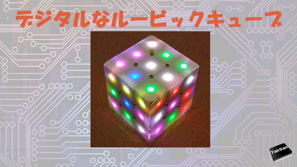
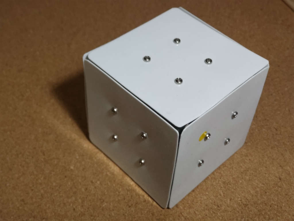
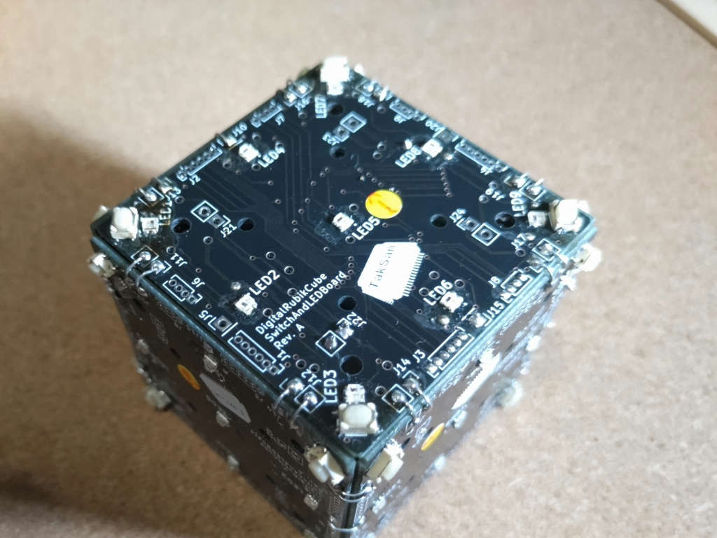
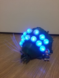
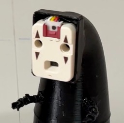
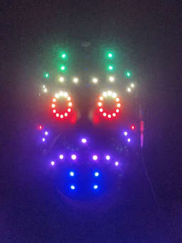
キューブの各マスの色を カラーLED で、回転するメカ部分を スイッチで置き換えて、デジタル化した、デジタルなルービックです。
-
 ハンドメイド優秀賞M5Stack Japan Creativity Contest 2024
-
 優秀賞Mouser Make Awards 2024
- 動画
-
- 開発素材
-
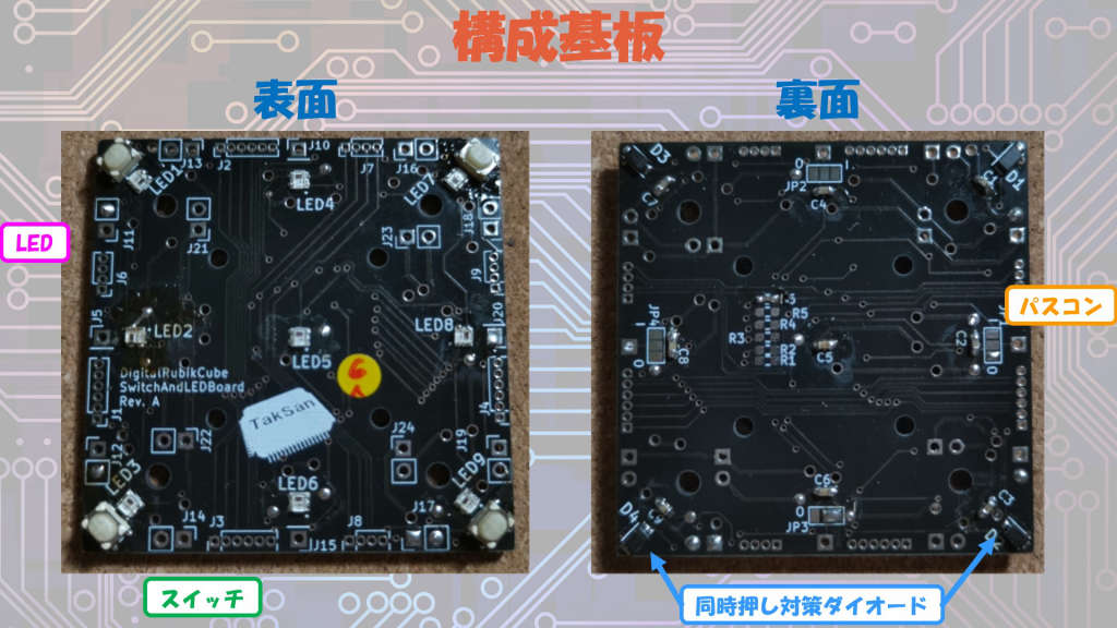
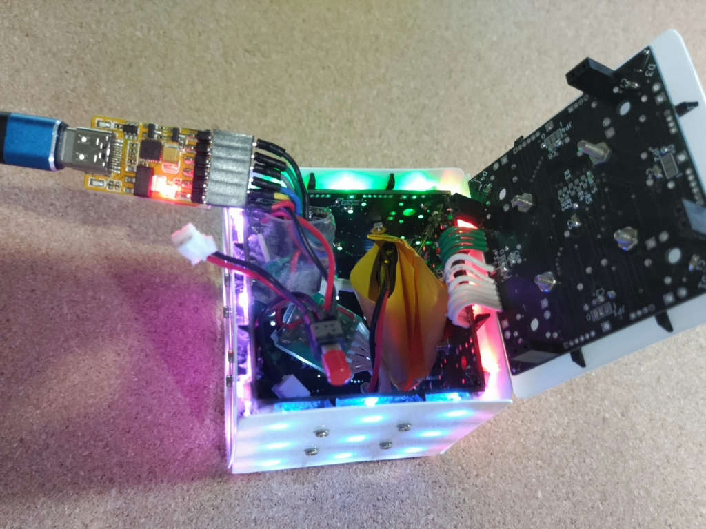
デバイス
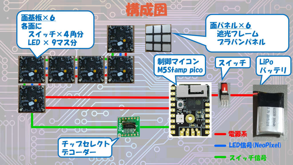
- システム構成
-
- ストーリー
-
- メンバー
-
-
- TakSan @taksan
-
- 全部
-
- 関連イベント
-
-
 Mouser Make Awards 20242024-04-01 開催
-
 テックシーカーコレクション20242024-07-06 開催
-
 M5Stack Japan Creativity Contest 20242024-06-01 開催
-
 ヒーローズ・リーグ 20242024-09-02 開催
-
 「Maker Faire Tokyo 2024」の出展作品まとめ(一部|非公式だよ)2024-09-21 開催
-
 アバナードHuman Impactリーグ2024-09-02 開催
-
- 同じニオイがする作品
-
-
 【簡単スマート管理システム】スマぽち
-
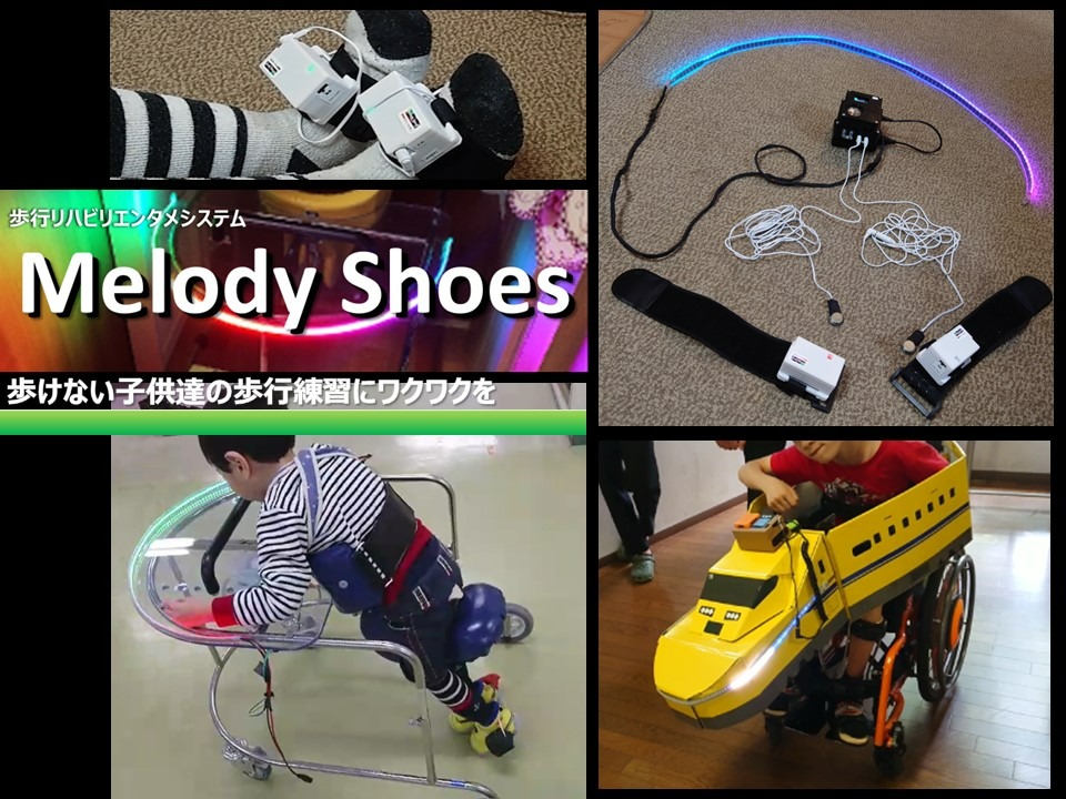 歩行リハビリエンタメシステム Melody Shoes
-
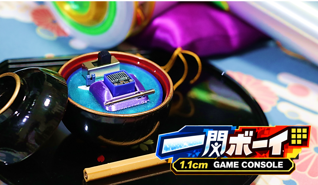 世界イチ小さい!?1.1cmのゲーム機 "一閃ボーイ!"
-
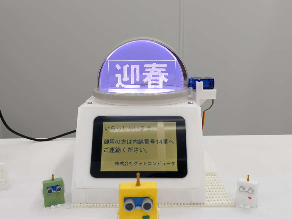 来客センサー(二代目)
-
Proto lovers ♥


189番目はRGBライトのルービックキューブで、デザインや制作が丁寧で、制作過程も細かい配慮があり、紹介されている内容もとても丁寧な作品です。自動的に実行させて、世界記録を目指すのはいかがでしょうか?
<最終審査員が選出>あきちかさん:オリジナリティ溢れる、ゼロから考えられた素晴らしい設計と、モノとしての完成度、機能としての完成度をとても感じました。基盤設計など電子工作的にも素晴らしく、かなり苦労されて設計されたのが伝わってきました。(講評を事務局が代筆)