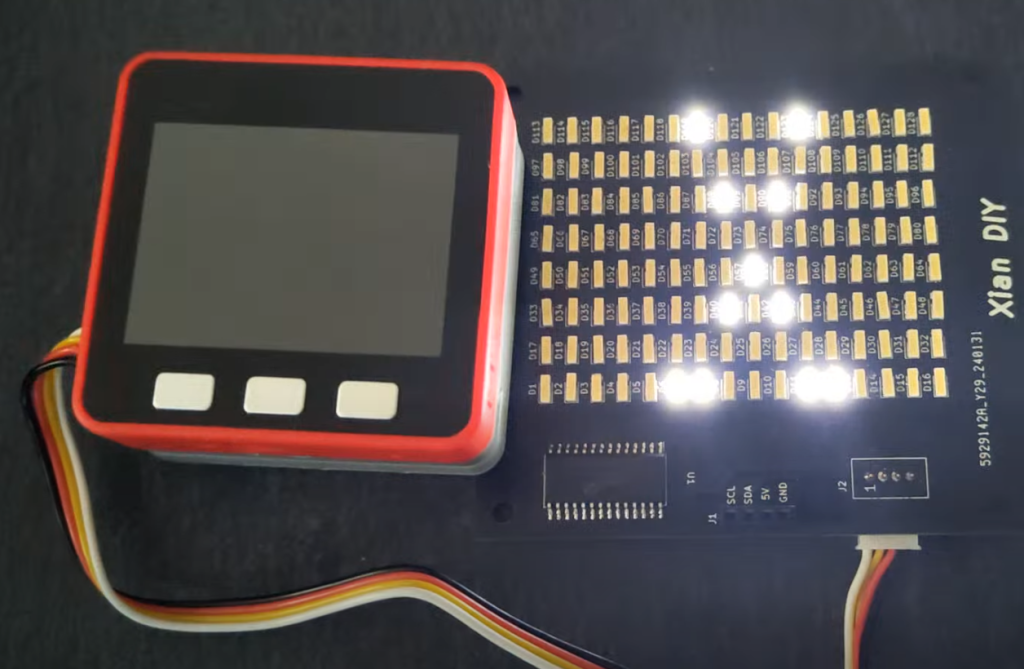
LEDマトリクスボードを自作してM5Stackで制御してみた
完成
© CC BY 4+
1161
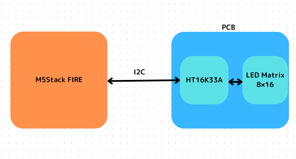
I played around with controlling an 8x16 LED matrix using M5Stack FIRE the HT16K33A matrix driver!
- 動画
-
- 開発素材
-
- システム構成
-
- ストーリー
-
- メンバー
-
-

- Xian DIY @xiandiy
-
-
- 関連イベント
-
-
 M5Stack Japan Creativity Contest 20242024-06-01 開催
-
- 関連リンク
-

-
-
- 同じニオイがする作品
-
-
 キャンプ感あふれるお天気グッズ「CAMP-CAN」by M5StickC PLus
-
 リア充サンタ帽
-
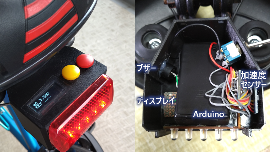 多機能!自転車用テールランプ
-
 世界で一番、プログラマっぽいCO2モニタ
-